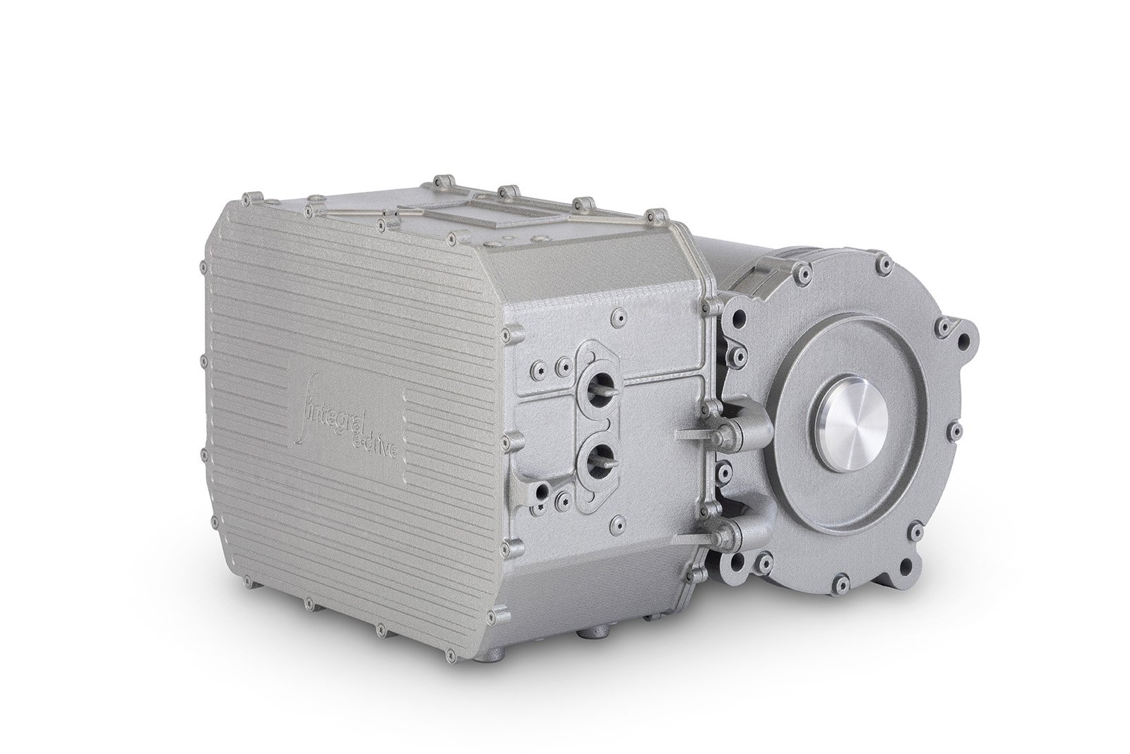
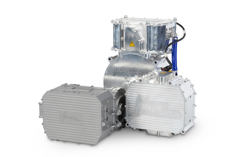
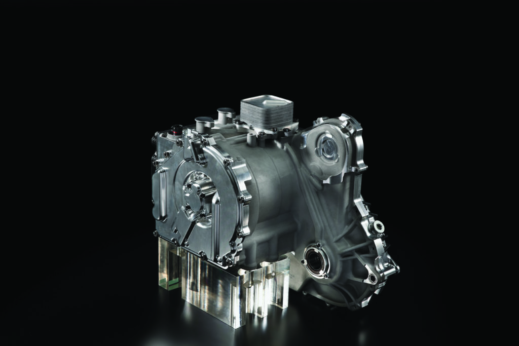
Alongside inverter technology, the capabilities of traction motors have increased massively in the past decade, with suppliers striving to produce designs with ever-greater power density; figures of up to 14kW/kg can be achieved with near off-the-shelf equipment. Traction motors all share two common components, a rotor and a stator. Normally, the rotor sits within the stator, but in some applications, such as certain in-wheel motor designs, an external rotor is used.
For motorsport applications, permanent magnet synchronous motors (PMSM) rather than induction motors are the norm, although there is ongoing development of high-performance induction machines by some companies. PMSMs use a rotor constructed from permanent magnets either mounted on the surface of the rotor or internally. The former approach gives greater performance (due to the magnetic material’s proximity to the stator) but is harder to engineer for higher-rpm applications due to the challenges of securing the magnets. The interaction between the rotating magnetic field of the stator (made up of multiple coils, usually copper, which are energized) and the constant magnetic field of the rotor creates a torque reaction, causing the motor to rotate. The speed of the motor is controlled by changing the magnetic field of the stator via a variable frequency drive (the inverter).
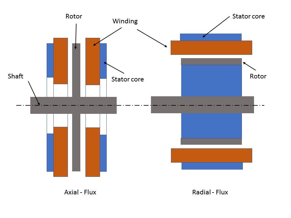
 Two main motor architectures dominate the market, radial and axial flux, which are distinguished by the magnetic fields within the motors. As the names suggest, in a radial flux machine the magnetic flux runs radially in relation to the rotational axis, and in an axial flux machine it runs parallel to this axis. Both motor topographies have their advantages and disadvantages in certain applications, though it is only in the last decade that axial machines have become more widely available. Axial flux machines are also known as pancake motors, as they tend to have a greater diameter than their length; for radial flux units, the opposite is true.

The mechanical advantage afforded by the axial flux design (where the magnets are mounted further from the rotational axis) means that, up to a point, they tend to have a greater power density potential than radial flux. The form factor also makes them ideal for packaging in P1 hybrid layouts where a motor needs to be mounted in-line with an engine and transmission. Axial flux machines do have some key limitations; for example, ensuring structural integrity in very high-rpm/high-power applications can be challenging due to the need to increase the rotor diameter. However, their ability to achieve excellent power density in a compact package has seen their adoption in a number of series.
This includes ETCR, which uses axial flux motors from supplier Magelec that are capable of 300kW contiguous power and 500kW peak, which is used as a push-to-pass function. At their current state of development, radial flux machines pip axial flux technology when it comes to ultimate power and efficiency. For example, Formula E initially saw a range of both motor types deployed by teams, as engineers worked out the most efficient means to maximize energy usage. Some used the high torque output of axial flux to reduce the number of transmission ratios needed and thus frictional losses, while others deployed a greater number of gears with higher-rpm radial flux designs.
However, advances in the latter’s design have seen their torque density grow along with operating speed, enabling their use with single-speed transmissions, for a more efficient overall drivetrain package. Now the entire field uses radial flux solutions, considered the most efficient approach under the current regulations. Beyond motor topography, a host of other factors dictate the achievable power density of a motor and, even more importantly, how long it can sustain high power outputs. These include the electromagnetic design, the magnetic material used, mechanical design elements such as the bearings and structural integrity of the rotor, and of utmost importance, cooling of the motor.
Material choices
Neodymium (NdFeB), a rare earth magnet and one of the strongest commercially available magnetic materials, remains a favored choice for high-power-density motor applications. It is, however, limited in its use by a relatively low resistance to temperature: above approximately 80°C it begins to lose performance, although different grades are available that can withstand higher temperatures. Motors using this material tend to also have very efficient cooling systems.
Another solution is to use magnets made from less potent materials that have a higher temperature resistance. For example, both of the MGUs fitted to Porsche 919 LMP1 used samarium magnets, in the case of the exhaust-mounted MGU because of the extreme temperatures the motor experienced, and on the front unit to ensure reliability. Although the front motor would normally operate within the range of neodymium materials, were there to be an issue with the cooling system and given the role of the car as an endurance racer, Porsche wanted the ability to run at elevated temperatures. The stator material also plays an important role in performance, with both the type of material and thickness of the laminates coming into play (this applies across both axial and radial flux motors).
It is notable that most regulations specify a minimum laminate thickness (0.1mm for F1, 0.05mm in Formula E). Thinner laminates are better as they reduce eddy current losses, but they are also fiendishly expensive to produce. In terms of materials, cobalt steel is often used for ultimate performance, with the role of the material being to facilitate the flow of the magnetic flux. Cobalt steel has a higher magnetic saturation point than standard electrical steels, so its use reduces losses and increases torque density. Among the other features that dictate performance is the fill factor of the stator windings (the amount of wire that can be crammed into the slots – the more the better). Here, there is interesting work ongoing to produce additive-manufactured copper motor windings, which can circumvent some of the issues limiting the traditional wire-based approach, not least the time-consuming production process. In the case of TU Bergakademie Freiburg’s Racetech Racing Team Formula Student Electric team, additive-manufactured windings enabled the realization of an ideal geometry that maximized fill factor while ensuring even cooling across the stator, reducing hot spots.

Cool headed
This leads to the subject of motor cooling, a perennial problem since the greatest heat concentrations within a motor tend to be in the most inaccessible areas. Liquid cooling is a must for most racing applications, and high-performance motor manufacturers have devised a variety of proprietary solutions to get coolant to where it is needed. The heat rejection from an electric motor is much smaller than that of a similarly powered IC engine.
A 200kW unit might reject only around 4kW, but if this is concentrated in the wrong area, it can still be an issue. A dedicated racing motor, for example, may have an air gap between stator and rotor of 0.5mm (the smaller the better for performance) and any heat concentration within that gap when the motor is under load can be decidedly problematic. Traditional approaches such as applying an indirect cooling jacket around the stator and relying on air cooling for the rotor are not sufficient in high-power-density applications. Instead, more advanced methods of cooling these parts are needed. For example, cooling channels can be incorporated within the stator itself or, in the case of the rotor, by channeling coolant through the rotor axle and into the rotor structure. Neither of these approaches is straightforward and various other elements of the motor, such as insulation around the windings, conspire against heat transfer out as the best electrical insulators form heat barriers.
It is also possible to directly cool some areas of a motor, such as the stator, using dielectric fluid, an approach that Porsche has developed for its recently revealed Mission E concept. This requires a reliable sealing solution between the stator and rotor but also makes for very efficient cooling of the windings and, moreover, also facilitates the use of smaller stator slots, the end result being potential for a considerable increase in power density. Electric motor and inverter technology will doubtless continue to evolve at a considerable rate, with ever-greater power density achievable and currently prohibitively expensive solutions becoming more cost-effective. This will in turn see electrification become more viable at all levels of racing in the coming decade, with the caveat that batteries remain high-cost components and technical regulations are still relatively immature.


