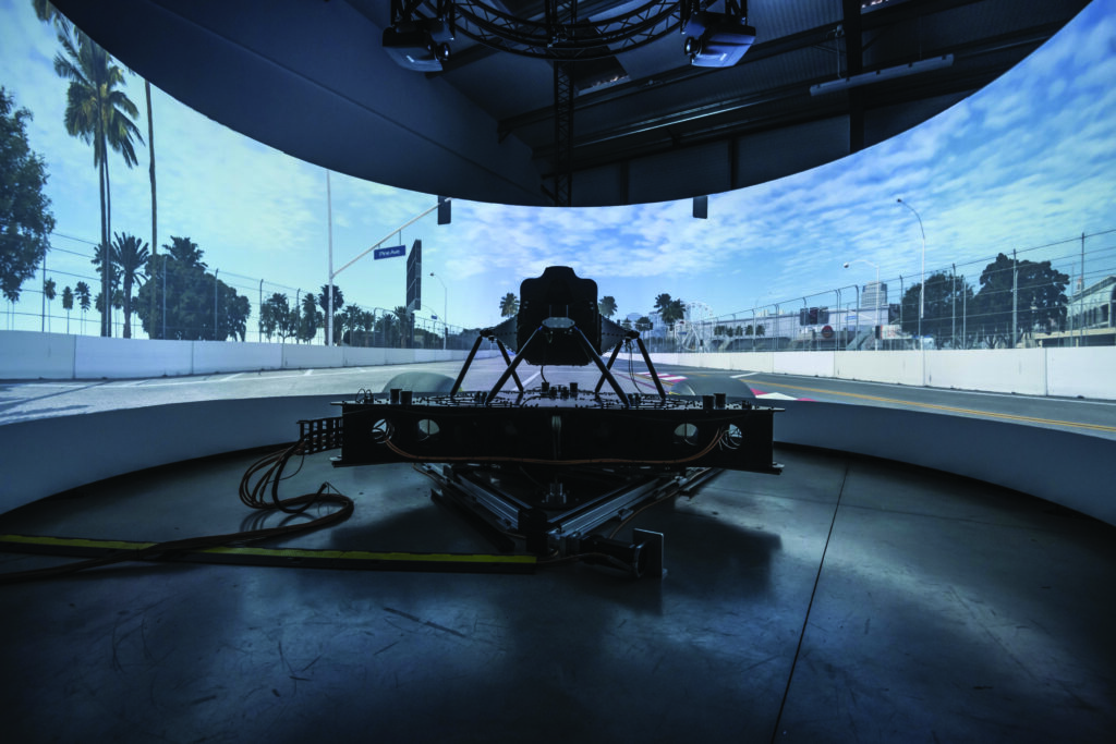
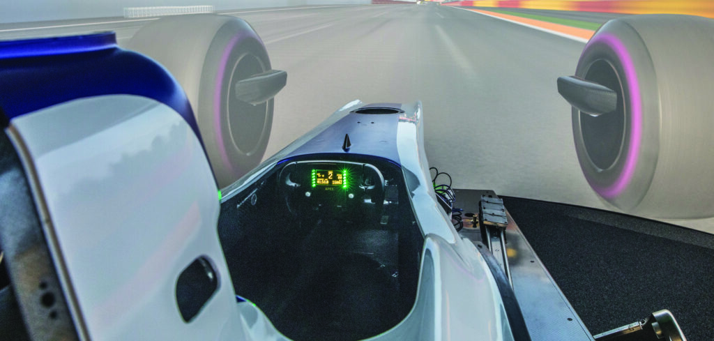
The last decade has seen driver-in-the-loop (DIL) simulators become indispensable vehicle development tools. The idea of using DILs for engineering tasks originated in the world of racing – first F1 and then other series – but more recently mainstream automotive manufacturers have recognized their benefits. BMW, for example, has installed no fewer than 14 examples of various types at its Research and Innovation Center (FIZ) in Munich.
DILs range from static units to those with full motion platforms, the latter being the focus of this article; specifically, how do different manufacturers quantify the capabilities of their systems and what impact does this have on the end user?
Professional Motorsport World spoke to four of the main suppliers to race teams and OEMs (at least two of which helped equip the BMW facility), canvassing opinions on what the most important performance parameters of a DIL are, and, critically, how they measure and report these.
Priorities
The consensus was that latency and the bandwidth of the motion platform sit high on the priority list, regardless of the intended end use. In the opinion of Dave Kirkman, technical director of simulation at AB Dynamics, “Latency, which is the delay between commanded input and platform response, and bandwidth, or frequency response, are two key performance indicators. However, they are intrinsically linked to the motion envelope of the simulator, both equally important for the platform choice,” he says.
He elaborates, “Typically, having a high bandwidth within ±3dB in the working range is the most important, followed by as low a latency as possible. Critically, maintaining this performance and latency with consistency across the range of motion is essential for ride and handling validation.
“Consistent performance across the range of travel is more desirable for overall simulator performance than peak figures,” he adds.
Ash Warne, CEO and chief engineer of new market entrant Dynisma, which has provided Ferrari’s motorsport operation with its latest DIL, flags signal-to-noise ratio, which can be used as a measure of the fidelity of a system, as another consideration.
“This dictates how the driver can pick up on very small differences from one scenario to another,” he explains. “This is incredibly important in a high-performance vehicle, where the driver is looking to pick up on tiny differences from one setup to another.” Ideally, a simulator will also be able to accurately reproduce subtle yet important effects, such as vibrations from the powertrain or tires, while eliminating any miscues that may stem from the mechanical operation of the motion platform itself.
Taking a wider view, Kia Cammaerts, technical director at Ansible Motion, emphasizes that the characteristics of a simulator can be broken down into three performance areas: physical, perceptual and integration. The physical relates to the motion platform, while perceptual covers anything that provides a sensory input, be that the vision system or haptic devices such as seat actuators and active pedals. The integration aspect encompasses both how components of the simulator interact and how the system coexists with the wider testing environment, for example, the addition of hardware-in-the-loop elements.
Reinforcing how each part of a simulator contributes to the overall performance, Edwin de Vries, CTO at Cruden, feels that visuals can trump motion in some use cases. “If you are doing experiments with ADAS and autonomous driving controllers, the visual system is the most important because it sets the perception of speed and place and it provides situational awareness,” he says. “Motion is second to visual, simply because you can drive without motion, but not visuals.”
As to how this translates into a simulator specification, he says, “You want a visual system with eye-limiting resolution (better than 2.4 arcmin/OLP) that covers the full field-of-view for the driver, and with a frame rate of more than 120fps to ensure smooth visuals.
However, in motorsport applications motion tends to take precedence. De Vries caveats, “Motion is key in evaluating driving performance when pushing a car to its limits, and this is why most motion systems innovations have their origin in Formula 1.”
How are these various performance parameters defined and measured? Taking the showpiece of a DIL, the motion platform, Cammaerts uses the following analogy: “All details are important contributors to the whole. It’s like conducting an orchestra. We need strong, cohesive contributions from our string, woodwind, brass and percussion sections in order to make good music. We recognize that there are some key instruments in an orchestra, like the piano, that can be central to a performance. And if there’s a piano in DIL, it’s the motion system.”
Quantifying performance
DIL simulator manufacturers are hardly unique in wanting their products to stand out from the crowd, with each touting its approach as the best available. However, a DIL is a sizeable investment for any organization, thus separating out subjective marketing claims from objective data is key when making a purchasing decision.
Part of this process hinges on ascertaining exactly what is shown by a manufacturer’s data. De Vries distills this by saying, “To measure is to know but only if you know what you are measuring.” Take latency, which in simplified terms can be defined as the delay between issuance of a command, for example, by the vehicle model, and the response of the motion platform. How should this be measured? Is it the time taken between the command and the start of movement, the completion of the movement or something in between? One needs to ask what the cause and effect being measured is and how the result is described.
Cammaerts explains that in the case of Ansible’s simulators, “The cause (or input) is always the timestamp of a vehicle physics calculation – any model-generated value that we might wish to use as a motion machinery command signal. The effect (or output) is always the timestamp of the response of a physical transducer that is located on the motion machinery itself.
“Fundamentally, what we’re after is a latency measurement that is relevant to DIL simulation, something that is a pure description of the amount of time it takes for vehicle physics commands to become human-detectable motions; specifically accelerations.
“Humans feel acceleration, not position, so we typically use a target of 90% of the demanded acceleration as the point to measure the latency.”
Both AB Dynamics and Dynisma state that their latency figures are based on the time between a command and achieving 100% of the demanded acceleration, as recorded by an IMU (inertial measurement unit) mounted on the motion platform. Warne notes, “Our motion generators achieve 100% of the demanded acceleration within our stated latency of 3-5ms. This is critical to allow the driver to respond in the way they do in the scenario under simulation.”
However, as de Vries highlights, the latency figure alone does not tell the whole story. For example, low latency can be achieved with very rapid acceleration of the platform, but this can result in an overshoot of the target value, leading to a miscue for the driver.
If damping is used to prevent this, the time taken to hit the target value is longer, but the chances of introducing misleading cues is removed. Obviously, the lower the threshold value, perhaps 50% compared with 90%, the lower the latency. Being able to achieve the low latency needed for a DIL capable of simulating even the highest-performance vehicles is in large part the job of the mechanical and electromechanical design of the platform. Kirkman summarizes, “DIL simulators require motors with low latency and high bandwidth with minimal backlash and cogging to instantaneously deliver the motor force directly to the platform.
“Therefore, any compliance in the system needs to be kept as close to zero as possible. A high-performance platform should be constructed to have the lowest mass and inertia combined with the highest stiffness possible.”
There are a host of other parameters relating to motion platform performance – for example, frequency response, which is an assessment of a motion system’s ability to deliver predictable dynamic content over a range of oscillation frequencies (bandwidth).
Unlike latency and acceleration, which are related to unidirectional movements, oscillations are by their nature bidirectional.
De Vries explains, “A frequency response function characterizes the dynamics of a motion platform, defining its ability to follow a sinusoidal input signal. It is a measure of attenuation and phase shift of platform accelerations as a function of input frequency. This applies to all 6DOF.” As to how frequency response is represented, Cammaerts says, “It is usually reported graphically, so that the magnitude and phase of an output can be viewed as a function of frequency, in comparison to an input.”
It is desirable that the magnitude and frequency plots are closely related well into higher frequency ranges, showing, for example, that modeled inputs match the physical responses of the simulator.
Manufacturers will use a variety of means to ensure the mechanical elements are performing in spec. According to Kirkman, AB Dynamics measures the accelerations from an IMU mounted on the platform surface and compares these with the inferred accelerations from the inverse kinematics. “These tests vary from performing single DOF chirp tests to full ride replays and white noise tests with all 6DOF being exercised simultaneously,” he explains. “This ensures cross-coupling behavior is not introducing artifacts into the IMU data.”
As has been highlighted, accurate and effective DIL simulation relies on the perfect coordination of a complex array of parameters. Even for an experienced simulation engineer, these can at times be bewildering. When assessing a new DIL, it is worth taking time to ascertain exactly what a given system can and can’t achieve, and how its performance is both measured and presented by a supplier, to ensure it can fulfill the engineering tasks that will be required of it.
One-size compromise
AB Dynamics’ Dave Kirkman makes an interesting simulator observation: “Traditionally, the industry has leaned toward investing in comprehensive simulators that can be used to develop all areas of a vehicle using one machine. This solution certainly has its place, but it can often result in a heavily compromised and expensive piece of equipment for any one test.” As the simulator market has matured, and the number of engineers vying for DIL time has increased, there is growing demand for simulators dedicated to specific areas of vehicle development.
Ash Warne of Dynisma agrees: “Within one OEM, there may be a requirement for several use cases which may or may not be served by the same simulator. For example, a focus of our systems is ride and NVH. Here the vertical dynamics of the simulator are incredibly important, as is being able to accommodate a representative mock-up of the real vehicle. Thus, a high payload capability is important. For vehicle dynamics and handling, the emphasis may be much more on the lateral dynamics and reproducing those faithfully. So, there is absolutely an opportunity for different simulators to serve different markets within automotive.” This should be taken into consideration, particularly for operations that span racing and road car development. The ideal simulator for developing a sports prototype, or even a hypercar, could be quite different from that for other, more mundane tasks.”


